Announcement

Due to the COVID-19 pandemic, all our offices are operating on a skeleton workforce. For inquiries, please get in touch with us via the emails listed on our contact page.
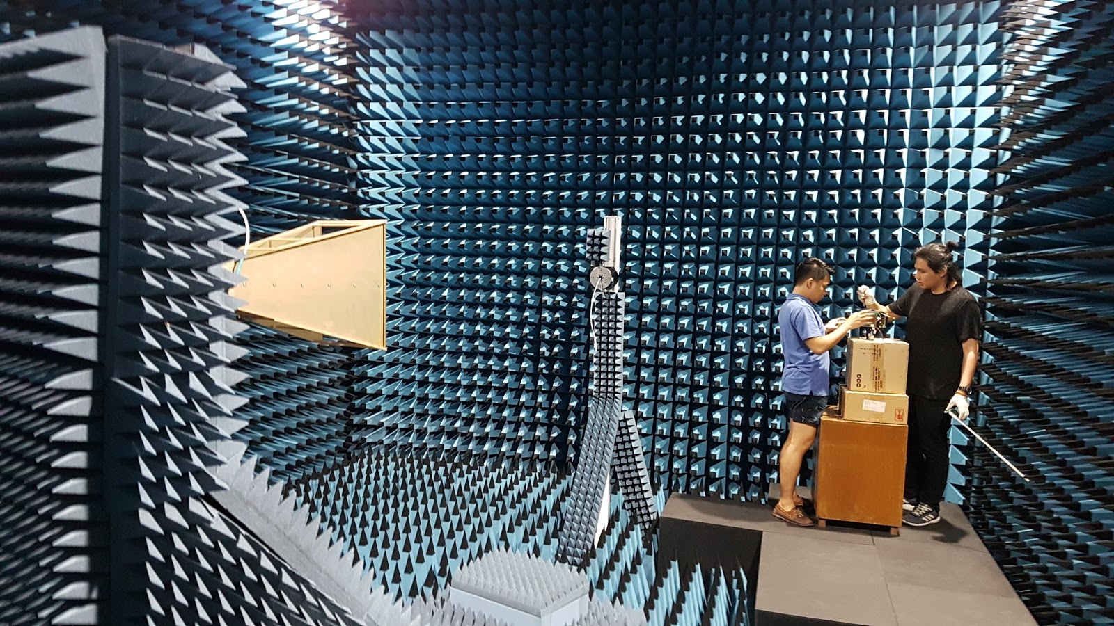
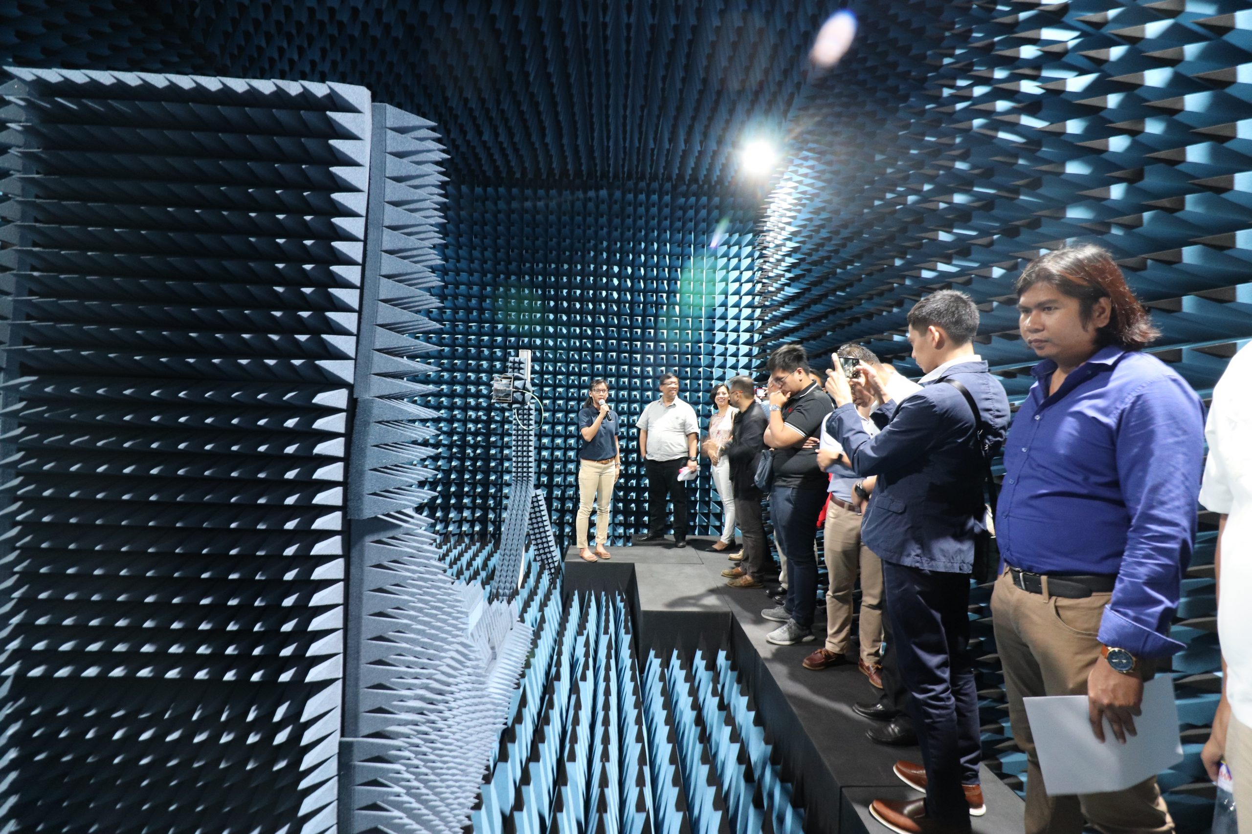
Full Anechoic Chamber
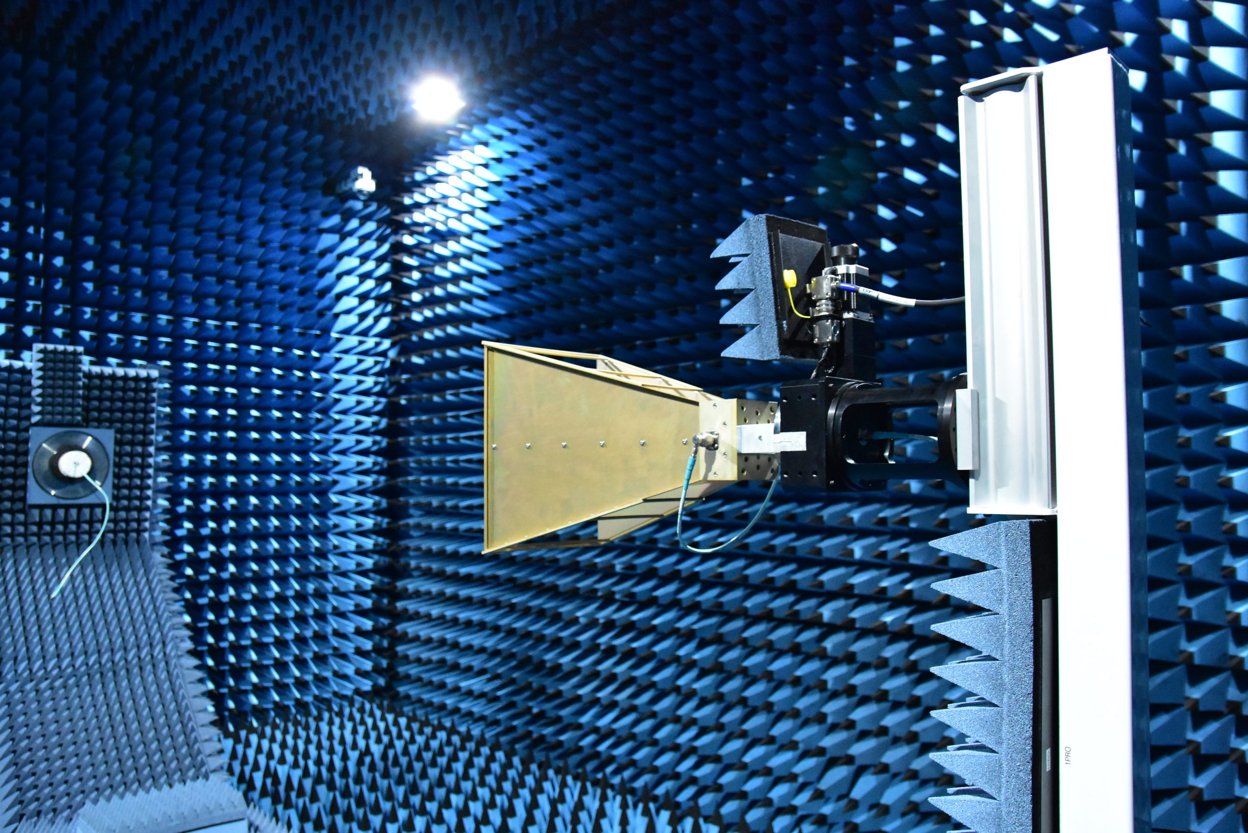
The full anechoic chamber is used to measure antenna radiation patterns. The frequency range of operation of the chamber is from 600 MHz to 26.5 GHz. It includes a spherical near-field system with a “roll over azimuth” L-bracket positioner for the Antenna-Under- Test (AUT) and a probe stand (as seen in ‘Chamber Layout’). An antenna measurement software is available for spherical near-field and quasi-far-field measurements.
The measurements are done inside a room with electromagnetic shielding. Additionally, the walls, ceiling, and floor of the interior are lined with specially treated pyramidal foam absorbers that prevent reflection of the electromagnetic and thereby emulating a free- space propagation environment. While mainly intended for antenna radiation pattern measurements, the chamber can also be used for other electromagnetic and radio frequency experiments or tests.
|
Frequency Range
|
600 MHz - 26.5 GHz
|
|
Chamber Dimension
|
8.08 m (L) x 6.48 m (W) x 5.2 m (H)
|
|
Antenna Positioner
|
dual-axis spherical positioner
|
|
Maximum Antenna Size
|
1.4 meters in diameter
|
|
Antenna Positioner Load
Capability
|
75 kgs
|
|
Radio Frequency Absorbers
|
45.7 cm pyramidal cone, floor absorbers are not mounted and can be removed.
|
|
Chamber Access
|
1.2 m (W) x 2.1 m (H) shielded auto-latching door
|
|
Chamber Power Outlets
|
3 sets with 2 220VAC, 60Hz outlets, with powerline
filtering
|
|
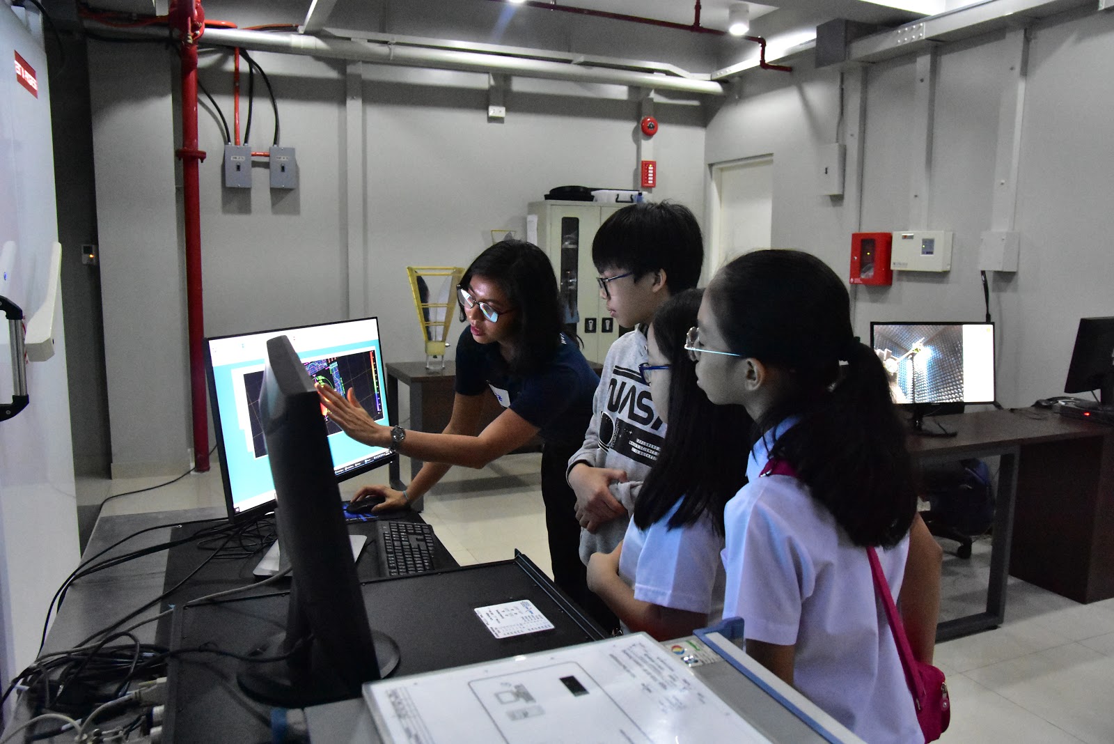
Test Viewing
|
Closed-circuit TV (CCTV) camera available inside
|
|
Vector Network Analyzer
|
Rohde&Schwarz ZVA40
|
|
Antenna Measurement Software
|
NSI2000
|
| Model Name | Frequency Range | Gain (dBi) |
|---|---|---|
| DRH370 | 370 MHz - 3 GHz | 3 - 16 |
| DRH10E | 698 MHz - 5 GHz | 3.5 - 16 |
| DRH50 | 4.5 GHz - 26.5 GHz | 6 - 20.5 |